Many people talk about speaker placement, and I agree this is very important. However, amplifier placement is also important. Why? It affects the damping factor at the speaker’s terminals.
Why is damping factor important?
The damping factor of an amplifier tells you how well it can control the load. In this case, the load is a speaker. As an example take a pen and try to write something on paper while holding it all the way at the end furthest from the tip. I think it is pretty difficult to write something with good accuracy this way. The further you put the amplifier away from the speaker the harder it will be for it to control it. This is because longer speaker cables have more resistance than shorter ones and therefore decrease the overall damping factor between the amplifier and the speaker.
What is damping factor?
By definition, the “damping factor” is the ratio of a speaker’s nominal input impedance to the amplifier output impedance:
—– Damping Factor = Speaker Impedance / Amplifier Output Impedance
On most amplifier specification sheets, the damping factor specifications assume an 8-ohm speaker impedance. When this is the case, the following equations can be used to determine the amplifier output impedance:
—– Damping Factor = 8 / Amplifier Output Impedance
or
—– Amplifier Output Impedance = 8 / Damping Factor
Damping Factor vs. Output Impedance
Damping factor and output impedance specifications describe the same amplifier characteristic but they do so in an inverse fashion. An amplifier with a high damping factor will have a low output impedance.
With 8-Ohm speakers, a damping factor of 10 is achieved when the amplifier output impedance is 0.8 Ohms. A damping factor of 100 is achieved when the amplifier output impedance is 0.08 Ohms. A damping factor of 1000 is achieved when the amplifier output impedance is 0.008 Ohms. The lower the output impedance, the higher the damping factor.
Speaker Impedance Plots
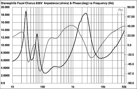
The plot to the left shows the impedance (solid black line) of a three-way speaker. This is a good example of a difficult-to-drive 8Ω speaker.
Notice that the impedance at 119 Hz is only 2.6 Ohms.
Also notice, that the impedance is 19 Ohms near 30 Hz, but just 6 Ohms near the 45 Hz lower limit of the speaker’s response.
The point of all of this is that speakers are not resistive loads. Speaker impedances change significantly, and often rapidly, across the audio band. These impedance variations can cause significant changes in the frequency response at the amplifier output if the amplifier’s output impedance is too high or the damping factor is too low.
Voltage Divider
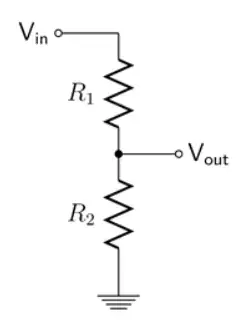
In the diagram to the left R1 represents the resistance of amplifier output + speaker cable and R2 represents the resistance of the speaker.
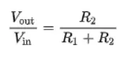
The transfer function is as follows:
Calculation Examples
Let’s look at two examples, one with a 10-foot speaker cable and another with a 1-foot cable. The cable is 16 AWG, which means that a 10-foot (actually 20 feet because there are two conductors) cable has a resistance of 0.0818Ω (20 x 0.00409Ω) and a 1-foot cable has a resistance of 0.00818Ω.
Looking at the Starkrimson Mono amplifier specifications which are found here, we see that this amp has a damping factor of 550, which is equivalent to an output impedance of 0.0145Ω (8Ω/550).
The damping factor at the speaker is determined by the total output impedance of amplifier + the resistance of the cables. For 10 and 1 foot cables we have the following:
—- 10 foot cable –> total impedance = 0.0145Ω + 0.0818Ω = 0.0963Ω –> damping factor = 83.07
—- 1 foot cable –> total impedance = 0.0145Ω + 0.00818Ω = 0.02268Ω –> damping factor = 352.7
From the speaker impedance curve above, we see that at 119Hz the impedance is 2.6Ω.
Similarly, at 3kHz it is 19Ω.
Using our 10 foot cable calculation, at 119Hz, R1 = 0.0963Ω, R2 = 2.6Ω
Using the transfer function equation we get a signal reduction of 2.6 / (2.6 + 0.0963) = 0.964 or -0.318dB
Using our 10 foot cable calculation, at 3kHz, R1 = 0.0963Ω, R2 = 19Ω
Using the transfer function equation we get a signal reduction of 19 / (19 + 0.0963) = 0.995 or -0.044dB
The difference between 119Hz and 3khz is 0.274dB
Using our 1 foot cable calculation, at 119Hz, R1 = 0.02268Ω, R2 = 2.6Ω
Using the transfer function equation we get a signal reduction of 2.6 / (2.6 + 0.02268) = 0.991 or -0.079dB
Using our 1 foot cable calculation, at 3kHz, R1 = 0.02268Ω, R2 = 19Ω
Using the transfer function equation we get a signal reduction of 19 / (19 + 0.02268) = 0.999 or -0.0086dB
The difference between 119Hz and 3khz is 0.07dB
The general rule of thumb for A/B and A/B/X tests is that levels should be matched to better than 0.1dB. If this is not done, the level changes can be detected by many listeners. In other words, a 10 foot 16 AWG cable will have a perceptible impact on the sound in a controlled test, even if it may go unnoticed in general listening.
Summary
Amplifier placement is important. This is because the closer the amplifier is to the speaker the shorter the cable that you can use.
Use speaker cables that are as short and as thick as possible to preserve the damping factor of the amplifier. In my experience, 10 AWG cables even at 6-feet long will have an insignificant impact on the sound.
Our Starkrimson Mono Premium amps are specifically designed to be small, allowing you to place them close to the speaker, allowing for very short cables.
References
(1) https://benchmarkmedia.com/blogs/application_notes/audio-myth-damping-factor-isnt-much-of-a-factor
(2) https://www.stereophile.com/content/focal-chorus-826w-30th-anniversary-edition-loudspeaker-measurements
(3) https://en.wikipedia.org/wiki/Voltage_divider
(4) https://www.engineeringtoolbox.com/copper-wire-d_1429.html
(5) http://www.sengpielaudio.com/calculator-db.htm
0 Comments